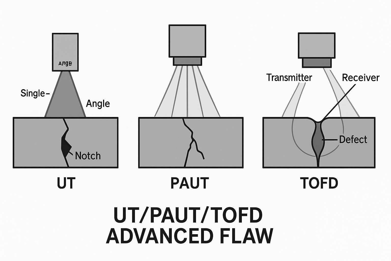
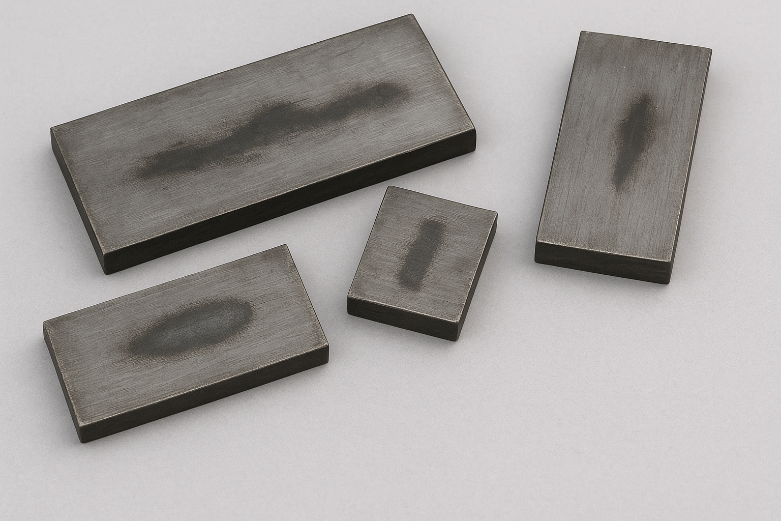
Advanced flaw samples for UT, PAUT, and TOFD are specialized test specimens designed to contain realistic, complex, and tightly controlled discontinuities. These samples are used for procedure qualification, performance demonstration, and advanced technician certification, particularly in high-stakes industries like oil & gas, nuclear, and aerospace.
Unlike basic calibration blocks (which use simple side-drilled holes or flat-bottom holes), these samples feature flaws that mimic real-world welding or manufacturing defects.
Structure of Advanced Flaw Samples
Advanced samples, often called Qualification Blocks or Demonstration Blocks, are typically full-scale mock-ups of critical components.
1. Material and Geometry
-
Material Match: They are made from the exact material and grade (e.g., SA516 Gr.70 Carbon Steel, Inconel, specific stainless steel alloys) and have the same thickness and joint geometry (e.g., Single-V butt weld, Double-V weld, pipe-to-nozzle joint) as the component being inspected.
-
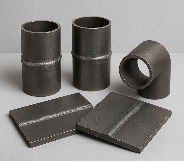
Weld Details: They contain an actual weld performed with the same welding process (e.g., GTAW, SMAW, SAW) used in production, complete with Heat-Affected Zones (HAZ).
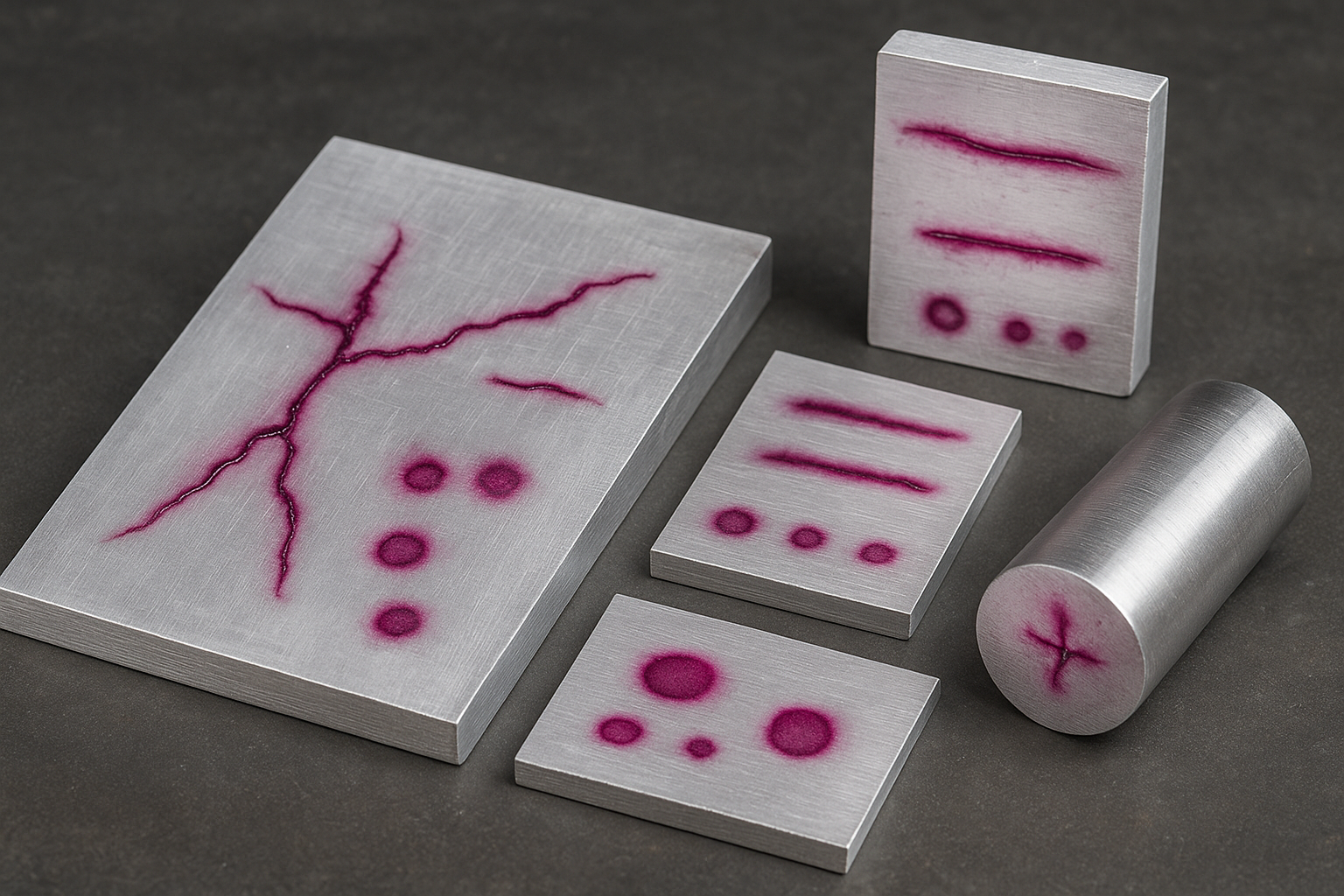
2. Flaw Characteristics
The flaws are deliberately introduced to challenge the advanced UT methods. They are typically planar (crack-like) defects, as these are the most critical for structural integrity.
| Flaw Characteristic |
Description |
Method of Creation |
| Planar Flaws |
Defects with a small through-wall dimension but significant length. Examples include cracks, lack of fusion (LOF), and incomplete penetration (IP). |
Mechanical fatigue, thermal shock, or intentional introduction of non-wetted surfaces during welding. |
| Complex Orientation |
Flaws are not always perpendicular to the scan surface. They may be skewed (transverse cracks) or misoriented relative to the weld fusion line. |
Precisely positioned EDM (Electrical Discharge Machining) or intentional pre-flaws introduced into the weld bevel. |
| Small Height ($h$) |
Flaws with extremely small through-wall heights ($h$), often below $1 \text{ mm}$ or $2 \text{ mm}$, forcing the NDT method to prove its sizing accuracy. |
Machining techniques, or embedding thin, non-wetted inserts (like Teflon or ceramic) during welding. |
Advantages for PAUT and TOFD
PAUT and TOFD are selected precisely because they can better detect and size the critical flaws contained in these advanced samples:
| Technique |
Sample Flaw Focus |
Key Advantage |
| PAUT |
Lack of Side Wall Fusion (LOF), Toe Cracks, Root Cracks. |
Beam Steering allows for optimal inspection angles across the weld volume and fusion line, and focusing provides better resolution near the surface and at the root. |
| TOFD |
Embedded Cracks and Volumetric Flaws (e.g., Slag). |
Accurate Flaw Sizing (especially height and depth) is achieved by measuring the time-of-flight of ultrasonic waves diffracted from the flaw tips, making the sizing amplitude-independent. |
| Combined |
Complex Weld Joints (Nozzle-to-Plate), Thick Sections. |
PAUT provides excellent detection and imaging (A-, B-, S-scans) while TOFD provides superior, accurate through-wall sizing of the detected flaws. |
These advanced samples must comply with stringent requirements from codes like ASME Section XI, Appendix VIII, API RP 2X, and API 1104, which dictate the number, type, size, and location of the flaws required for a valid qualification test.

Reviews
There are no reviews yet.