
Machined Block Samples
Description
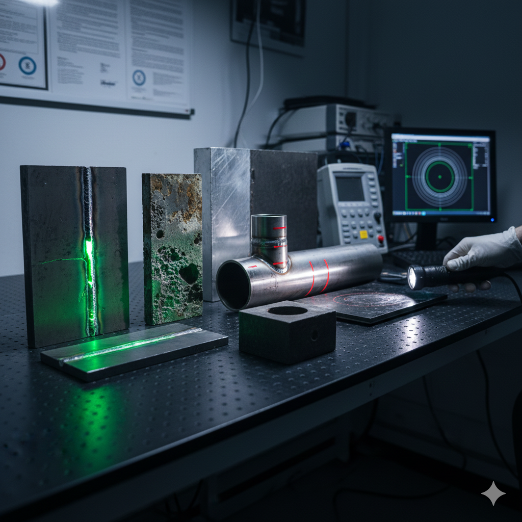
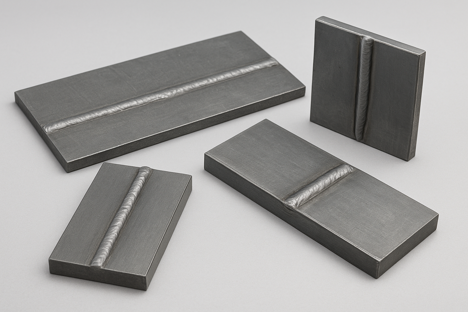
Machined block samples are reference standards used extensively in Non-Destructive Testing (NDT), particularly Ultrasonic Testing (UT), for calibrating equipment, verifying test procedure accuracy, and certifying personnel.
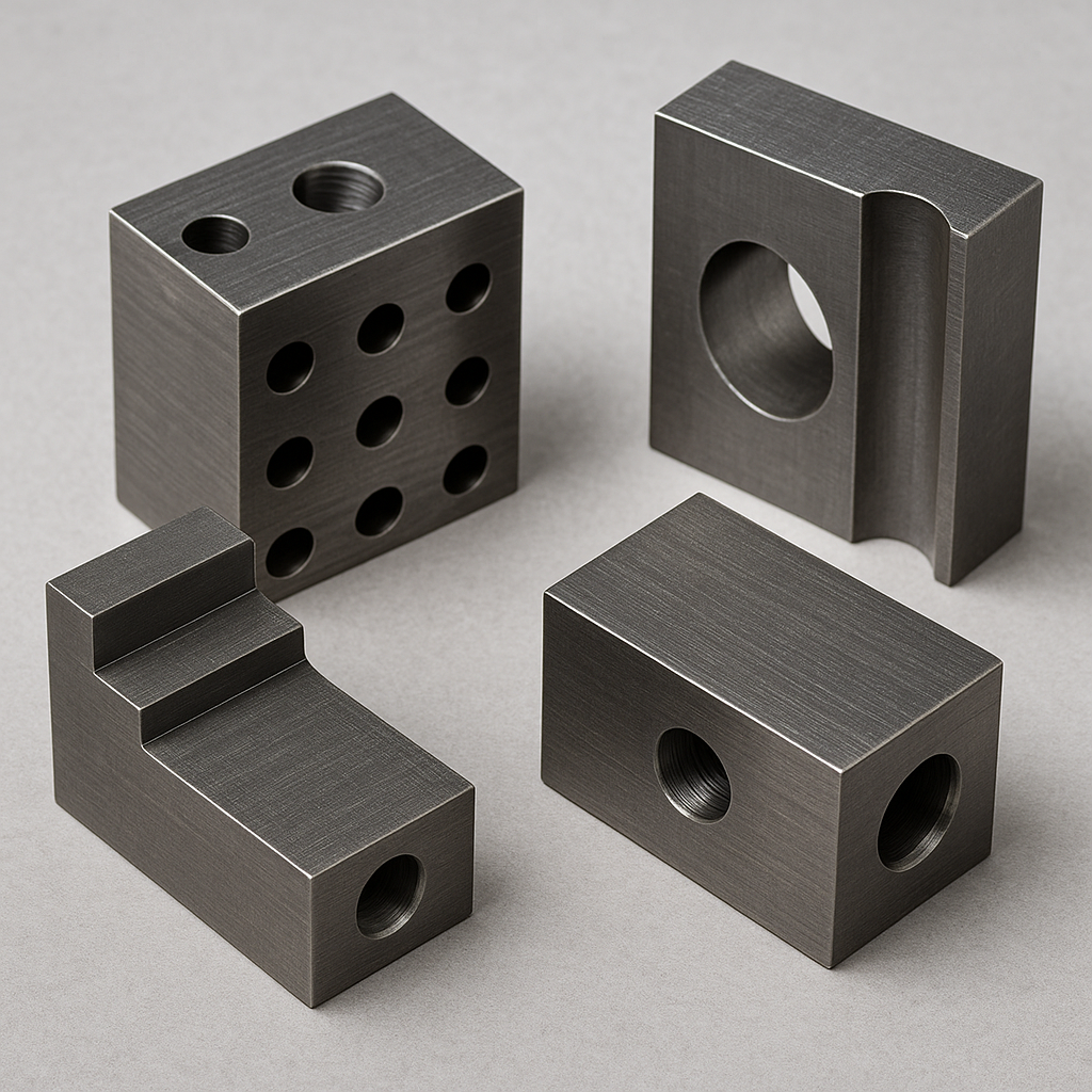
These blocks are characterized by their precision-machined features (like holes, steps, and notches) of known dimensions, which serve as artificial discontinuities to compare against real flaws found during inspection.
Primary Role: Ultrasonic Calibration Blocks
The most common application of machined blocks is in the calibration of ultrasonic flaw detectors and thickness gauges. The machining process ensures the reference reflectors are highly reproducible and accurately positioned.
1. Thickness Calibration Blocks (Step Wedges)
-
Structure: A block machined into a series of steps with precisely known, certified thicknesses (e.g., a 5-step or 10-step block).
-
Purpose:
-
To set the sound velocity in the material.
-
To check the linearity and accuracy of the thickness gauge across its measurement range.
-
2. Distance and Area Amplitude Blocks (DAC/Area Sets)
These blocks contain carefully machined features used for quantitative flaw evaluation:
| Block Type | Machined Features | Purpose |
| Distance Amplitude Correction (DAC) Blocks | A set of blocks, all with the same size Flat-Bottom Hole (FBH), but drilled at varying depths (Metal Travel Distance). | Used to generate a DAC curve, compensating for signal loss (attenuation and beam spread) so flaws of the same size generate the same echo amplitude regardless of depth. |
| Area Amplitude Blocks | A set of blocks, all with the same Metal Travel Distance (depth), but with FBHs of varying diameters (e.g., from $1/64^{\prime\prime}$ to $8/64^{\prime\prime}$). | Used to verify the relationship between flaw size and echo amplitude, ensuring the instrument can accurately distinguish between different-sized flaws. |
3. IIW and AWS Blocks
These are standard, intricately machined blocks used for specialized calibration, primarily for weld inspection:
-
IIW (International Institute of Welding) Blocks: Contain precision Side-Drilled Holes (SDH), a $100 \text{ mm}$ scale, and a $50 \text{ mm}$ radius corner. Used to set sound velocity, refracted angle, and the beam index point (the sound exit point on the transducer).
-
AWS (American Welding Society) Blocks: Such as the AWS Resolution Calibration Block (RC block), which contains precisely spaced through-holes to verify the system’s ability to resolve two closely spaced discontinuities.
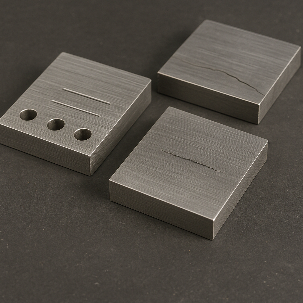
Flaws Related to Machining
While most defects found in machined blocks are artificial features for calibration, the components that have undergone machining may develop secondary processing discontinuities that NDT must detect:
-
Grinding Cracks: Fine surface cracks caused by excessive localized heat build-up during grinding, leading to thermal stress. These are typically shallow but sharp and are best detected by Magnetic Particle Testing (MT) or Liquid Penetrant Testing (PT).
-
Machining Tears/Laps: Surface flaws caused by the tool tearing the material rather than cutting cleanly, often due to dull tools or incorrect feed rates. These are detected by surface NDT methods (MT/PT).
-
Heat Treatment Cracks: While not a direct result of machining, they often initiate at stress concentration points created by sharp corners, keyways, or threads that were finished by machining before heat treatment. These are critical and checked by MT/PT.
Reviews
There are no reviews yet.