
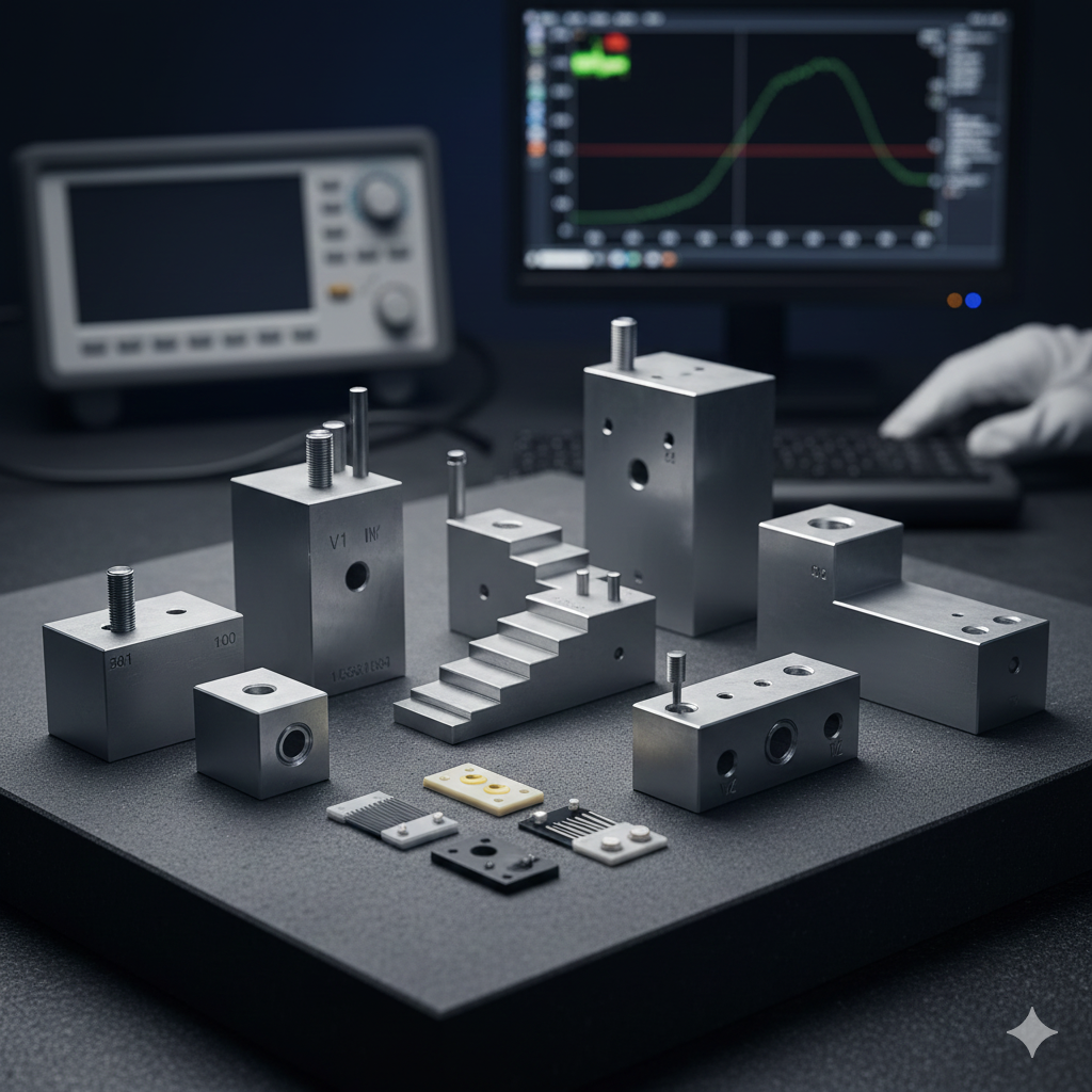
Calibration Blocks & Standards
Description
Calibration Blocks & Standards
Calibration blocks and reference standards are specialized, precisely manufactured test specimens essential for ensuring the accuracy, consistency, and reliability of Non-Destructive Testing (NDT) equipment. They are used to verify and adjust the instrument’s settings before, during, and after an inspection.
General Purpose and Importance
-
Equipment Calibration: The primary function is to adjust the NDT instrument (e.g., ultrasonic flaw detector, eddy current gauge) to ensure it measures accurately. This includes setting the sensitivity, zero point, and time base/range (metal distance).
-
Reference and Standardization: They contain artificially induced flaws (like side-drilled holes, notches, or flat-bottom holes) of known size, depth, and location. Inspectors use these known defects to establish a consistent reference for interpreting signals from actual, unknown flaws in the test component.
-
Traceability and Compliance: Using standardized blocks allows for results to be compared across different equipment, inspectors, and inspection dates, ensuring compliance with international standards (e.g., ASTM, ISO, AWS, ASME).
-
Material Matching: For methods like Ultrasonic Testing (UT), the calibration block material (alloy and heat treatment) should be the same as the material being inspected to ensure that the sound velocity and acoustic properties are matched, guaranteeing accurate results.
Types of Calibration Blocks (Primarily Ultrasonic Testing)
Ultrasonic Testing (UT) uses the widest variety of blocks, each designed for a specific calibration purpose:
| Calibration Block Type | Primary Use / Function | Key Features |
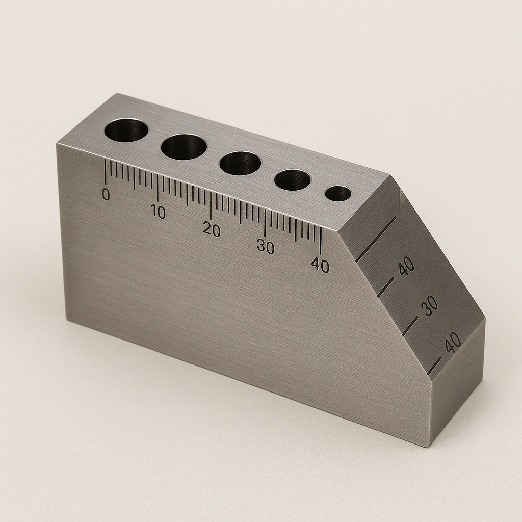
| IIW-Type Blocks (V1 & V2) | Velocity, Timebase/Range, and Angle Beam Calibration. | Contains radii, angled surfaces, and side-drilled holes for setting the sound exit point (beam index) and refracted angle of angle-beam transducers. |
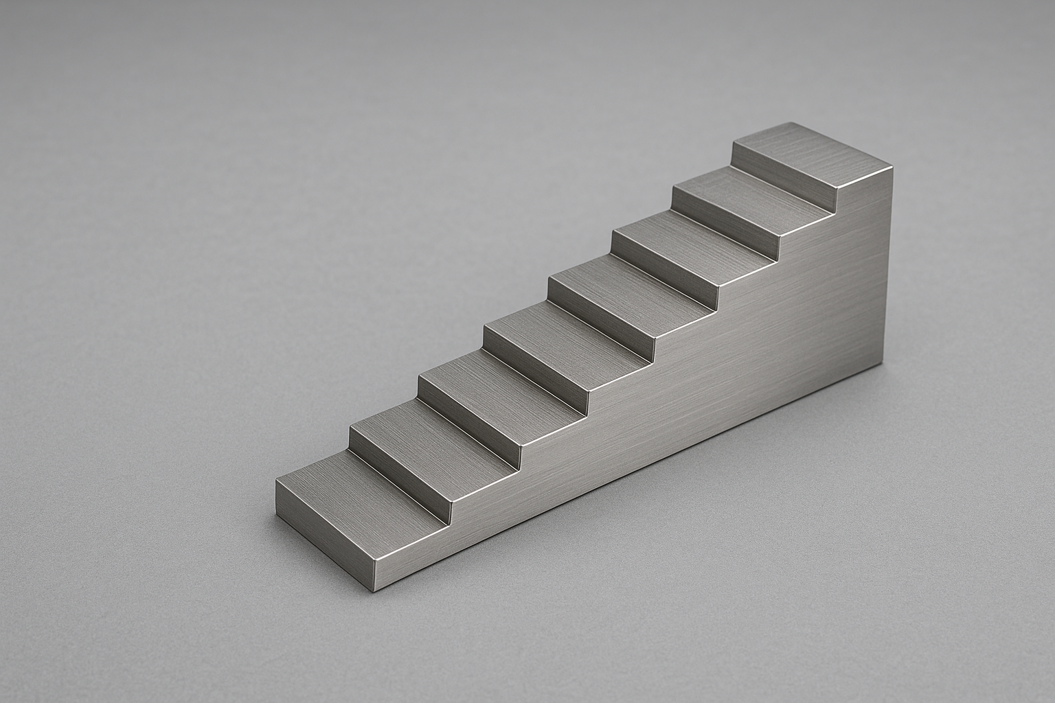
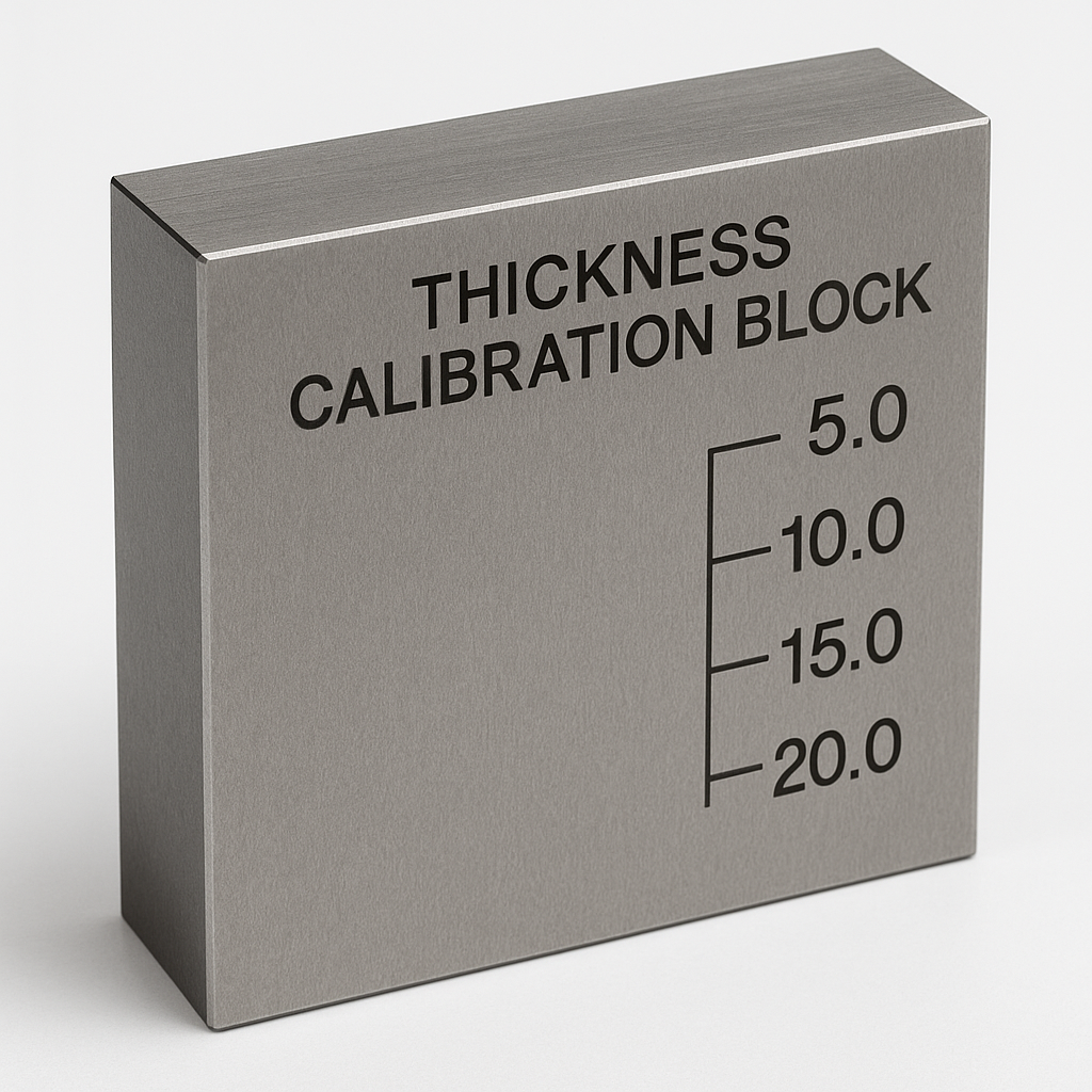
| Step Wedges | Thickness Measurement and Linearity Calibration. | Features multiple steps with known, varying thicknesses. Used to calibrate and verify ultrasonic thickness gauges across a range of values. |
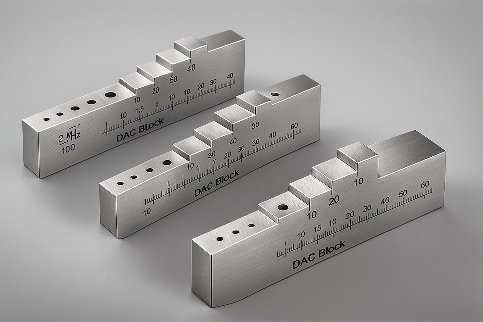
| Distance Amplitude Correction (DAC) Blocks | Sensitivity and Flaw Sizing (DAC Curve). | A set of blocks (or one block with varying depth features) containing flat-bottom holes of the same size but at different metal distances (depths). This allows the inspector to create a curve that corrects for the natural attenuation of sound energy as it travels further. |
| Area Amplitude Blocks | Flaw Sizing (Area Comparison). | A set of blocks containing flat-bottom holes at the same metal distance but with varying hole diameters (areas). Used to relate the flaw signal amplitude to a known reflector area. |
| ASME/AWS Blocks | Weld Inspection Standards. | Specifically designed to meet codes like ASME Section V or AWS standards for shear wave (angle beam) inspection of welds, often featuring side-drilled holes and notches in specific geometries (e.g., DSC, DC, SC blocks). |
Standards in Radiographic Testing (RT)
In Radiographic Testing, the term Image Quality Indicator (IQI), also known as a penetrameter, is used instead of a calibration block.
-
Purpose: IQIs do not calibrate the X-ray machine itself, but rather confirm that the radiographic technique has sufficient sensitivity and contrast to reveal a certain level of detail.
-
Types:
-
Wire-Type IQI: Consists of a set of wires of varying diameters encased in a plastic or flexible sheet. The number of visible wires determines the image quality level.
-
Plaque-Type IQI (Hole-Type): A small plaque of the test material with three drilled holes corresponding to 1T, 2T, and 4T of the plaque’s thickness. The minimum hole size that can be clearly seen is a measure of image quality.
-

Reviews
There are no reviews yet.