
AWS Resolution Calibration Block
Description
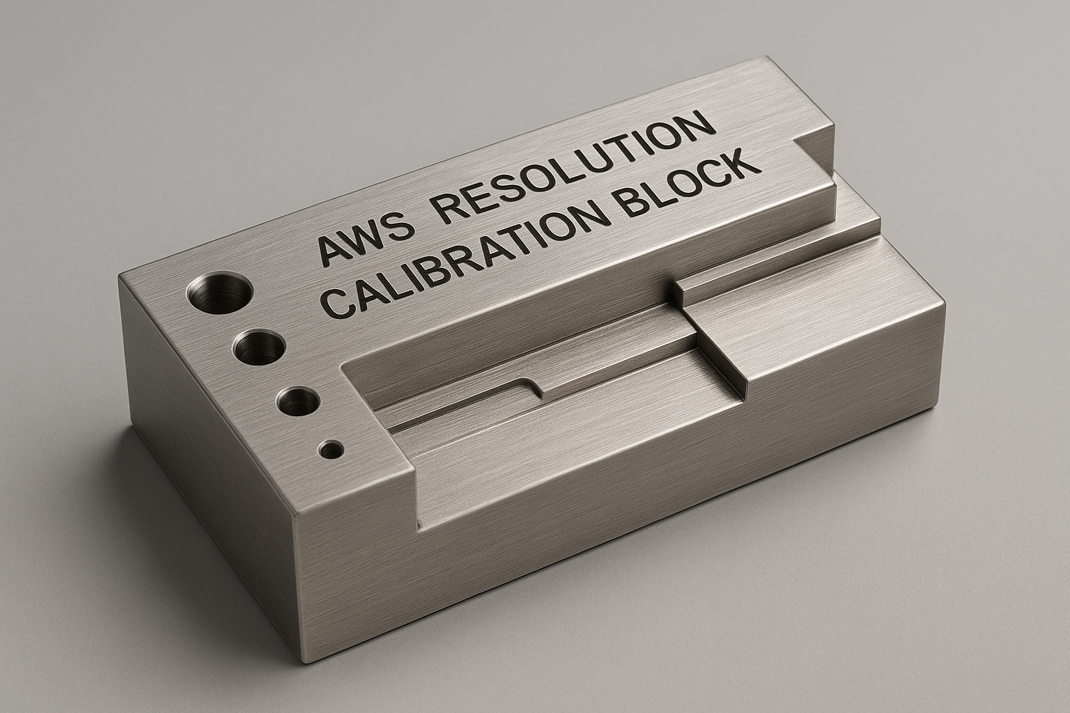
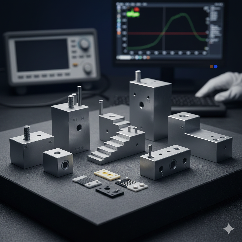
The AWS Resolution Calibration Block, often referred to as the RC block, is a specialized reference standard used in ultrasonic testing (UT) to assess the resolution capability of angle beam transducers.
It is one of the mandatory calibration blocks specified by the American Welding Society (AWS) Structural Welding Code, AWS D1.1, for the ultrasonic inspection of welds in steel structures.
Purpose
The primary function of the AWS Resolution Block is to verify that the ultrasonic testing system (flaw detector and angle beam transducer) can effectively resolve, or distinguish, between two discontinuities that are close together in the sound path.
Specifically, it is used to check the transducer’s:
-
Near-Surface Resolution (or Far-Field Resolution): The ability to resolve flaws at short or long distances from the transducer index point.
-
Angle Beam Resolution: The check is conducted for the specific refracted angles used in weld inspection.
Structure and Features
The AWS Resolution Block is precisely machined and certified for its dimensions and reflector locations.
-
Material and Dimensions: It is typically a rectangular block, often made of carbon steel (or acoustically equivalent material) and has nominal dimensions of $6.0^{\prime\prime} \times 3.0^{\prime\prime} \times 1.0^{\prime\prime}$ (or $152.4 \text{ mm} \times 76.2 \text{ mm} \times 25.4 \text{ mm}$).
-
Reflectors (Holes): The block contains three sets of two through-holes (a total of nine holes) of a standard diameter, usually $\mathbf{0.0625^{\prime\prime}}$ ($\mathbf{1.6 \text{ mm}}$).
-
The holes are arranged in sets, with each set corresponding to a specific refracted angle ($\mathbf{45}^\circ, \mathbf{60}^\circ,$ and $\mathbf{70}^\circ$).
-
The two through-holes within each set are spaced at different depths (sound path distances) to test the system’s ability to resolve the echoes from two closely spaced reflectors.
-
Calibration Procedure
During the resolution check, the technician performs the following steps:
-
Transducer Placement: The angle beam transducer is placed on the block surface and positioned to transmit the ultrasonic beam through the designated set of holes (e.g., the $\text{60}^\circ$ set).
-
Signal Maximization: The technician adjusts the instrument gain and transducer position to maximize the echoes from the two holes in the set.
-
Resolution Check: The system successfully passes the resolution check if the display (A-scan) shows two distinct and separate peaks corresponding to the two holes. The valley between the two peaks must drop to a specified percentage (e.g., $20\%$ or $40\%$) of the peak amplitude, as defined by the applicable procedure or standard.
If the instrument only shows a single, broad echo, the resolution is insufficient for the requirements of the AWS D1.1 code, and the transducer/instrument combination must be adjusted or replaced.
Other AWS Calibration Blocks
The AWS Resolution Block ($\mathbf{RC}$) is often used in conjunction with other AWS-specified blocks for a complete calibration, which include:
-
DSC Block: Used for Distance, Sensitivity, and refracted angle Calibration.
-
DC Block: Used primarily for Distance and beam index Calibration.
-
SC Block: Used primarily for Sensitivity and refracted angle Calibration.
The combination of these blocks ensures the UT instrument is correctly set up for the complex inspections required by the AWS code.
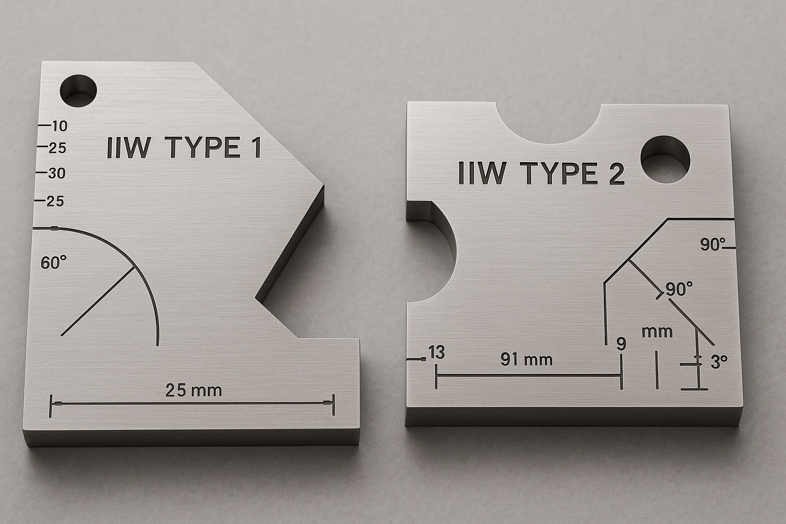
Would you like to compare the AWS Resolution Block with another standard calibration block, such as the IIW Block (International Institute of Welding)?

Reviews
There are no reviews yet.