
Welded Plate Samples
Assured
Returns
Enquiry
Support
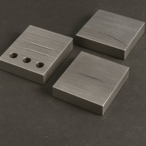
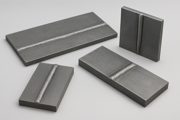
Welded plate samples are standardized test specimens used in Non-Destructive Testing (NDT) primarily for qualification, calibration, and training related to the inspection of welded joints.
These samples contain actual welds and are critically important because they allow NDT technicians to practice finding and characterizing flaws in a controlled, realistic environment that closely mimics in-service components.
Primary Uses of Welded Plate Samples
1. NDT Procedure Qualification
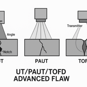
Major codes, such as ASME and AWS D1.1, require that NDT procedures (especially for advanced methods like Phased Array UT) be proven effective before they are used on critical components. A welded plate sample matching the material, thickness, and joint design of the production weld is used for this purpose. The sample contains known, manufactured flaws to demonstrate that the proposed procedure can reliably detect and size them.
2. Personnel Qualification and Certification
Welded plate samples (often called Flawed Specimens or Demonstration Blocks) are used to test and certify NDT personnel. Technicians must demonstrate proficiency by accurately locating, identifying, and sizing the concealed flaws within the sample using the specified NDT method.
3. Equipment Calibration and Setup
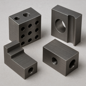
For techniques like Ultrasonic Testing (UT), a special type of welded plate sample, known as a Calibration Block, is used to:
-
Set up the sound velocity and beam angles on the flaw detector.
-
Establish a reference sensitivity, often using a small, precisely drilled Side-Drilled Hole (SDH) or notch placed within the plate or the weld volume.
Common Flaws in Welded Plate Samples
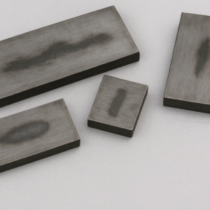
For NDT training and qualification, flaws are intentionally introduced into the weld joint of the plate sample to simulate real-world welding defects. These flaws are designed to challenge the NDT method's capabilities.
| Flaw Type | Description | NDT Technique Focus |
| Cracks | Linear, sharp discontinuities caused by stresses, especially toe cracks, root cracks, and transverse cracks. | UT, RT, MT (surface) |
| Lack of Fusion (LOF) | Failure of the weld metal to fuse with the base metal or previous weld passes, often appearing on the sidewall of the weld prep. | UT, RT (for severe cases) |
| Incomplete Penetration (IP) | Failure of the weld metal to completely fill the root of the groove joint. | UT, RT |
| Slag Inclusions | Non-metallic compounds (oxides, flux) trapped within the weld metal. | RT, UT |
| Porosity | Spherical gas pockets trapped in the weld, often appearing as clusters. | RT (as distinct circular indications), UT |
Standards and Configuration
The design and required features of welded plate samples are strictly defined by industry codes to ensure consistency and traceability.
-
AWS D1.1: Specifies the configuration of test plates (e.g., thickness, groove angle, backing strip) for qualifying welders for different weld positions (e.g., 1G, 3G, 4G).
-
ASME Section V: Mandates the use of reference reflectors (like SDHs or notches) placed in a calibration block or a mock-up of the component for calibrating volumetric NDT methods like UT and Radiography (RT).
Welded plate samples can be created as Full Penetration Groove Welds or Partial Penetration Groove Welds, matching the exact joint geometry of the final component.
No Reviews Yet
Be the first to share your experience with this product.
Get a Quote for Welded Plate Samples
Our NDT specialists will respond within 24 hours with pricing, specifications, and lead times. For urgent requirements, reach us directly via WhatsApp or phone.